

Natural Gas Pressure Reducing Valves for Safe Pipelines
- 2026-08-28 09:20:43
- admin
- NO COMMENTS
The first warning at a natural gas pressure-reduction station is often heard rather than seen. A low metallic buzz develops around the regulator body when demand falls at night. The downstream gauge moves, steadies, then moves again. On the next inspection round, the stem response feels slow and a faint gas reading appears near a packing or impulse-line connection. Nothing has tripped, yet the station is no longer behaving as it did after commissioning.
Engineers pay attention to that change because small instability can grow through a very direct chain. Inlet pressure fluctuates, the plug begins to hunt around its seat, repeated micro-movement wears the guiding surfaces, and response becomes slower just when demand changes quickly. A second chain can start after a large pressure drop: the gas cools, moisture or heavy hydrocarbons collect at a restriction, friction rises, and the valve starts to stick. The consequence is not limited to poor control. It can become a downstream overpressure event, an interruption to customers, or a release of flammable gas.
How Pressure Reducing Valves for Natural Gas Transportation Enhance Safety and Compliance
Introduction
Significance of Pressure Regulation
Transmission pipelines move large volumes efficiently at pressures that downstream mains, metering equipment, industrial users, and service regulators may not be designed to accept. A pressure reducing valve creates a controlled transition between those pressure zones. It must absorb changing differential pressure while keeping the outlet close to its setpoint as inlet pressure and gas demand move through the day.
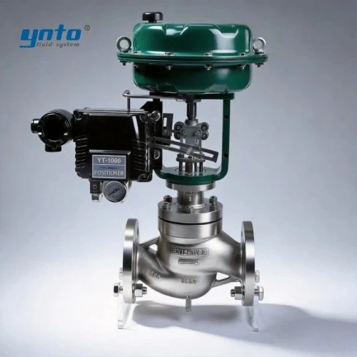
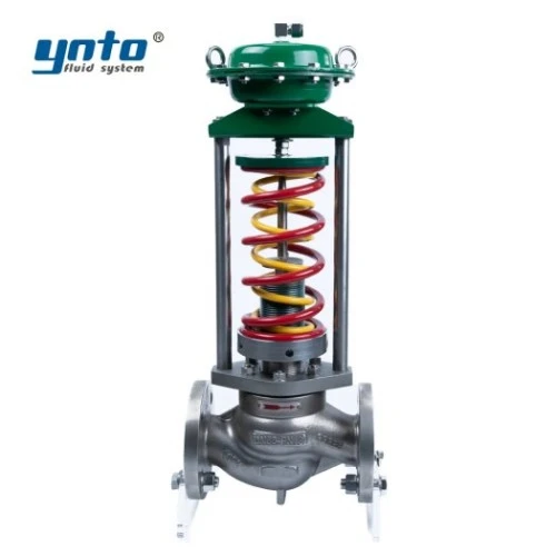
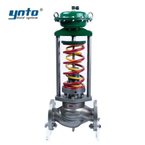
That sounds simple until the station is viewed as a complete system. The regulator, sensing line, filter, heater, relief or safety shut-off device, isolation valves, instruments, and bypass all influence the result. For straightforward duties where external power is undesirable, a self-operated pressure control valve can use process pressure to position its trim. Selection still depends on inlet and outlet pressure, required capacity, shutoff behavior, gas composition, noise limit, temperature, and the minimum controllable flow.
Current Challenges in Natural Gas Transportation
Modern networks rarely operate at one design point. Compressor dispatch changes inlet pressure, industrial loads start and stop, and seasonal demand widens the flow range. Renewable gas or hydrogen blending may also alter density, sealing behavior, and measurement assumptions. A regulator sized only for peak flow can be too large at minimum demand, where small movements create large flow changes and downstream pressure begins to oscillate.
Gas quality adds another layer. Rust scale, pipe debris, compressor oil, condensate, and ice can restrict a pilot or scoring-sensitive trim. Engineers in field operations often notice the result as a slow recovery after a load change, an increasing pressure drop across the upstream filter, or different setpoints needed to obtain the same outlet pressure. Those observations are more useful than waiting for a high-pressure alarm.
The Mechanics of Pressure Reducing Valves
Operating Principles
A direct-operated regulator balances downstream pressure against a spring or other loading force. When outlet pressure falls, the sensing element allows the plug to open farther; as outlet pressure rises, the valve moves toward closed. Pilot-operated designs use a smaller pilot to control loading pressure on the main actuator, which can provide higher capacity and tighter regulation but introduces small passages that demand clean gas.
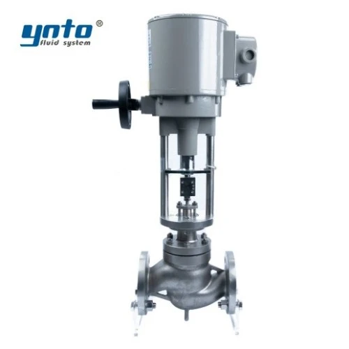
The important engineering question is not merely whether the valve opens. It is whether the complete force balance remains stable throughout the specified flow range. Excessive gain, an oversized orifice, poor sensing-line location, or mechanical friction can make the regulator chase its own correction. When a powered loop is preferable, the wider YNTO control valve range allows engineers to compare self-operated, pneumatic, and electric arrangements rather than forcing one mechanism into every pressure-reduction duty.
Integration into Gas Compression Systems
At compressor stations and city-gate facilities, regulation is coordinated with filtration, heating, metering, overpressure protection, and emergency isolation. A scrubber or filter removes liquids and solids before they reach small pilot passages. Where pressure reduction causes strong cooling, heating or staged reduction may be needed to prevent hydrates, ice, or hydrocarbon condensation from interfering with the trim.
Control philosophy matters as much as piping. In monitor-and-worker service, one regulator controls normally while the other takes over if pressure rises. Parallel runs add capacity or redundancy, but their setpoints and droop must be coordinated. A bypass must not become an uncontrolled route around protection. Commissioning should verify fail positions, control-line routing, relief capacity, alarms, and valve response—not simply a changing PLC display.
Ensuring Safety in Gas Distribution Systems
Identifying Risks without Proper Regulation
Without reliable regulation, downstream equipment may exceed its design pressure. Flanges, instrument tubing, meter bodies, and customer regulators then become potential leak points. Gas released into a poorly ventilated area can create a fire or explosion hazard; an outdoor release still requires ignition control, gas detection, an exclusion zone, and an emergency procedure.
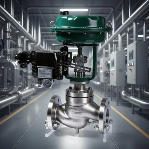
Underpressure also matters. A regulator that sticks too far closed can interrupt burners or process equipment, and an unstable supply may cause repeated trips. High differential pressure can generate damaging aerodynamic noise and vibration; low-flow operation can produce plug chatter. For severe service, a sleeve-guided design such as a pneumatic sleeve control valve may improve trim stability, but only after sizing confirms that its rangeability, leakage class, actuator thrust, noise treatment, and fail action match the gas duty.
Case Examples of Malfunctions
Consider a station that controls by day but cycles at night. Nothing is broken; the regulator is operating below its stable range because its flow coefficient is too large. The plug approaches the seat, pressure rises, the valve closes, pressure falls, and the cycle repeats. Vibration then wears the seat and guide, turning a sizing error into leakage and delayed response.
In another pattern, fine rust restricts a pilot filter and distorts the pressure signal, so the main valve responds late to rising demand. Adjusting the spring masks the symptom; cleaning the pilot path and checking filtration addresses the cause. Rising isolation-valve torque gives a third warning: temperature cycling hardens the seal, friction increases, and the actuator stalls during an emergency test.
Compliance with Industry Regulations
Overview of Regulatory Bodies
For U.S. pipeline operators, PHMSA regulations in 49 CFR Part 192 are central. Section 192.739 requires covered pressure limiting and regulating stations to be inspected and tested at intervals not exceeding 15 months, but at least once each calendar year. Section 192.741 addresses recording or telemetering pressure gauges for specified distribution arrangements. State rules may add obligations.
ASME B31.8 covers the design, fabrication, installation, inspection, and testing of gas transmission and distribution pipeline facilities, including compressor, metering, and regulation stations. ANSI-recognized ASME B16.34 influences pressure-temperature ratings, materials, examination, testing, dimensions, and marking for applicable valve construction. API 6D is important for associated pipeline isolation valves. It should not be misrepresented as a complete performance standard for a pressure regulator.
International projects may use ISO 23555-2 for regulator safety, construction, performance, testing, and documentation within its scope. DIN EN 334 addresses regulators up to 10 MPa and influences construction, sizing, testing, marking, and records. Specifications must identify the governing edition and jurisdiction; mixing standards without a compliance matrix creates gaps rather than extra safety.
How Compliance Affects Valve Selection
Compliance changes what a buyer must request. A purchase description that says only “DN100 pressure reducing valve” omits the information that determines safety: maximum and minimum inlet pressure, controlled outlet range, maximum allowable operating pressure, normal and peak flow, gas composition, design temperature, allowable noise, leakage class, failure position, connection standard, hazardous-area needs, and required test documentation.
Material selection follows the same logic. Carbon steel is common for many transmission and distribution bodies, but low-temperature properties must be checked where pressure reduction causes strong cooling. 316L can suit selected wet or mildly corrosive services, while Duplex may be considered for more demanding chloride-bearing environments after a proper corrosion review. PTFE can provide low-friction sealing in suitable temperature and pressure ranges. For sour gas, material hardness and resistance must be assessed against the applicable sour-service requirements rather than inferred from an alloy name. External FBE coating may protect buried or exposed steel, but it does not correct an incompatible wetted trim.
The Importance of Monitoring and Testing
Gas Pressure Monitoring Techniques
A local gauge shows the present condition. A transmitter and historian show what happened at 02:00 or during compressor changeover. Useful monitoring includes upstream and downstream pressure, filter differential pressure, temperature before and after reduction, valve position, and high-high or low-low alarms independent enough to reveal a failed control signal.
Trend shape often tells the story. A repeating saw-tooth outlet trace suggests hunting. Increasing filter differential pressure points toward contamination. A growing difference between commanded position and actual travel can indicate friction, actuator weakness, or positioner error. Where a pneumatic control loop is used, an electro-pneumatic positioner can improve positioning and provide a clearer relationship between signal and travel, provided instrument air is clean, dry, and available at the required pressure.
Utilizing Flow Measurement Devices
Pressure data alone cannot distinguish every fault. A falling outlet pressure during a genuine demand surge is different from the same pressure fall with unchanged flow. Orifice plates and other differential-pressure devices can be engineered under ISO 5167 principles, while ultrasonic gas meters used for custody-transfer and allocation duties are addressed by ISO 17089-1. Meter choice depends on range, pressure loss, accuracy, gas quality, straight-run availability, calibration strategy, and whether the reading is for control, balancing, or billing.
For diagnostics, engineers compare flow, pressure, temperature, and valve position on one time axis. Rising travel without more flow suggests a restriction; increasing flow without corresponding travel may indicate bypass leakage or measurement error. Instruments therefore support more than accounting. They reveal deterioration before a regulator reaches an alarm limit.
Best Practices for Valve Maintenance
Scheduled Inspections
A useful inspection program follows failure modes, not a generic checklist. Leakage surveys, setpoint and lock-up checks, safety-shutoff verification, control lines, filter differential pressure, actuator travel, vent condition, corrosion, vibration, and noise need acceptance criteria. The interval must satisfy regulation while reflecting station criticality, service history, cycling, and gas cleanliness.
Intrusive work requires isolation, depressurization, specified purging, gas testing, ignition control, permits, and confirmation that the network remains protected. Replaced diaphragms, seats, springs, and pilots should be traceable. After reassembly, technicians must complete required tests and record as-found and as-left values; otherwise the trend needed to adjust maintenance intervals is lost.
Troubleshooting Common Issues
When outlet pressure oscillates, first compare actual flow with the valve’s controllable range. Then check sensing-line location, trapped liquid, pilot cleanliness, filter restriction, spring setting, actuator friction, and interaction with parallel regulators. When the valve responds slowly, verify signal and supply pressure before dismantling the body. When leakage appears, identify whether it is external, through-seat, or from a vent; each points to a different risk and repair path.
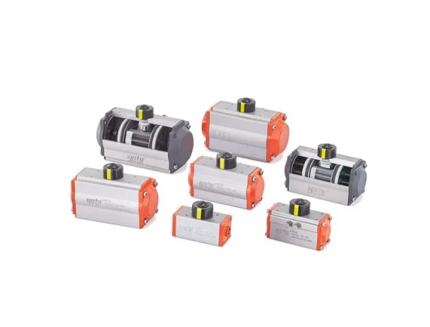
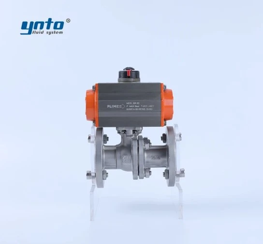
Avoid compensating for mechanical faults through repeated setpoint changes. A technician can make a sticky regulator appear stable for one operating condition, only for it to fail when demand moves. Likewise, an actuator should not be increased in size without checking allowable stem force and mounting loads. YNTO’s pneumatic actuator options can support automated isolation and control packages, but actuator selection must be based on break torque or thrust at the maximum differential pressure, safety factor, operating speed, air supply, and required fail-safe action.
Conclusion
Recap of Safety and Compliance Importance
Pressure reducing valves make natural gas transportation usable at each downstream pressure level, but their safety contribution depends on more than holding a nominal setpoint. Stable sizing, clean sensing paths, appropriate materials, reliable overpressure protection, accurate monitoring, and disciplined maintenance work together. Pressure fluctuation that leads to trim vibration, or contamination that delays a pilot signal, can progress from a small operating clue to leakage, overpressure, or loss of supply.
For procurement teams, the practical lesson is clear: specify the operating envelope and governing standards before requesting a quotation. Ask for capacity calculations, material details, leakage and pressure-test criteria, actuator or regulator response, documentation, and maintenance requirements. A valve that fits between the flanges is not necessarily a valve that will control safely.
Looking Ahead: Innovations in Pressure Reducing Technology
The next generation of regulator stations will rely more heavily on redundant digital pressure sensing, remote diagnostics, valve-travel signatures, and analytics that identify hunting or friction before a trip occurs. Smarter monitoring does not replace mechanical protection. Relief devices, monitor regulators, slam-shut functions, and fail-safe isolation remain essential because sensors and communications can fail.
For engineers planning a new station or replacing an unstable regulator, YNTO can review pressure, flow, temperature, gas composition, materials, actuation, control signals, and applicable standards before recommending a configuration. That application review is where safety and commercial value meet: the objective is not the most complex valve package, but a maintainable system that controls across real demand conditions and produces the records needed for compliance.
- 2026-10-09 14:26:55
.png?imageMogr2/format/webp)
- 2026-09-30 08:25:23
- 2026-09-28 10:28:43